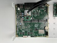
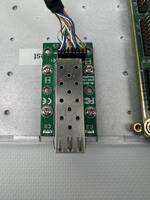
In this blog post, we will show how to use an SFP port with a PC Engines APU board. We will detail each step, from required equipment to verification of proper operation, through the possible boards settings or equipment mouting in an S2 RackMatrix case.
1. Required hardware
- An APU 2/3/4 board
- One 1-SFP port mini-PCIe card, Intel i210-AS BL-GES210S
- A Rack-Matrix S2 case to hold the SFP slot properly
2. Compatibles Ports
To start, here the compatible mini-PCIe sockets allowing to use a SFP card with APU boards.
Warning, there is a hardware difference between the APU2C and APU2D (and following). Electronic modification changed the default behavior. It is required to update the BIOS and select the right setting to enable SFP card detection.
APU 2C
| Connector | Buses | Up-to-date BIOS | |
| J12 | msata | ||
| J13 | PCIe / USB / SIM | 1igb0 | |
| J14 | PCIe / USB | igb3 | igb4 |
1 with coreboot v4.0.30, the "m" setting must be enabled in the BIOS. See below
m Force mPCIe2 slot CLK (GPP3 PCIe) - Currently Enabled
APU 2D and next
From APU2 version D, setting in the BIOS is the inverse in comparison to APU2 version C.
| Connector | Buses | Up-to-date BIOS |
|
| J12 | msata | ||
| J13 | PCIe / USB / SIM | 2 igb0 |
|
| J14 | PCIe / USB | igb3 | igb4 |
2 With coreboot v4.12.0.4, the "m" setting must be disabled in the BIOS. See below
m Force mPCIe2 slot CLK (GPP3 PCIe) - Currently disabled
APU 3
| Connector | Buses | |
| J14 | mSATA + USB + SIM2 | |
| J15 | USB + SIM1 | |
| J16 | PCIe + USB |
APU 4
| Connector | Buses | |
| J13 | msata | |
| J14 | USB/SIM | |
| J15 | PCIe + USB |
2. Readying S2 case
3. Plugging the mini-PCIe SFP card to an APU board
3.1 Plugging the cable on the mini-PCIe card side
3.2 Plugging the cable on the SFP port side
4. Checking the full set
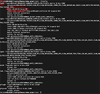
4.1 pfSense CE
Test done with pfSense CE 2.5.0 and an APU2E board. SFP card is set up on port J13 (middle mini-PCIe socket) and can be found as igb0.
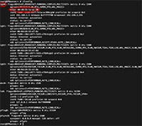
4.2 OPNsense
Test done with OPNsense 21.1 and an APU2E board. SFP card is set up on le port J13 (middle mini-PCIe socket) and can be found as igb0.


