")
")
Tutorials
20
November
2020
Mounting of the LED and push button report on an APU
This tutorial will explain how to mount the LED and push report RMT-CASE-M1-ACC0003 for a PC Engines APU1, APU2, APU3 or APU4
Please have the following items ready:
- soldering iron tool
- 5.5 mm hex screwdriver
- Phillips screwdriver
Table of Contents
- Presentation
- Step 1 - Solder the 8 pin header connector
- Step 2 - Unsolder the SMC LED from the motherboard
- Step 3 - Fixing the motherboard and mounting the spacer braces of the LED report
- Step 4 - Mounting of the LED report
- Step 5 - Connection of the LED report cable
- Step 6 - Final mounting, overview
Presentation
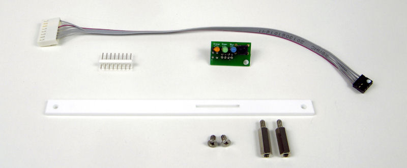
Content of the kit RMT-CASE-M1-ACC0003.
Please locate on the following image the locations of the 8-pin connector to be soldered and the SMC LEDs to be desoldered
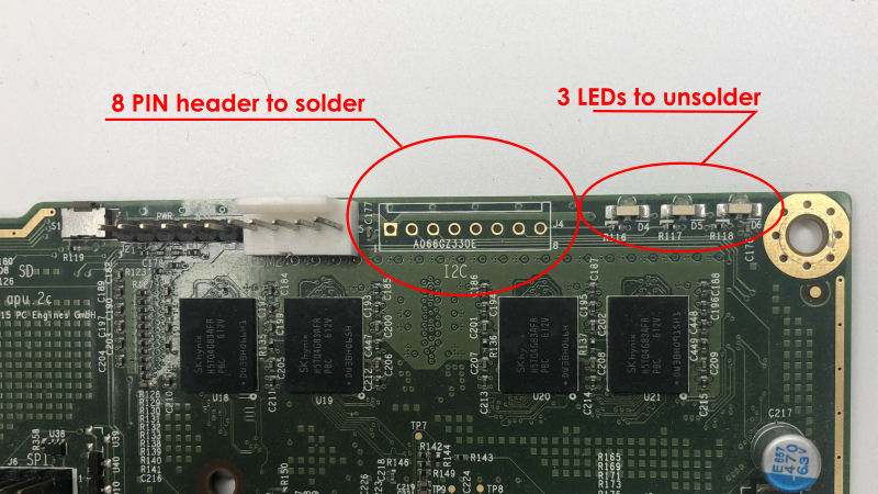
Step 1 - Solder the 8 pin header connector
This step is used to solder the 8-pin male connector to receive the LED and push button report cable.
Solder the 8 pin header connector on the following location J4 on an APU2, J5 on an APU3.
Step 2 - Unsolder the SMC LED from the motherboard
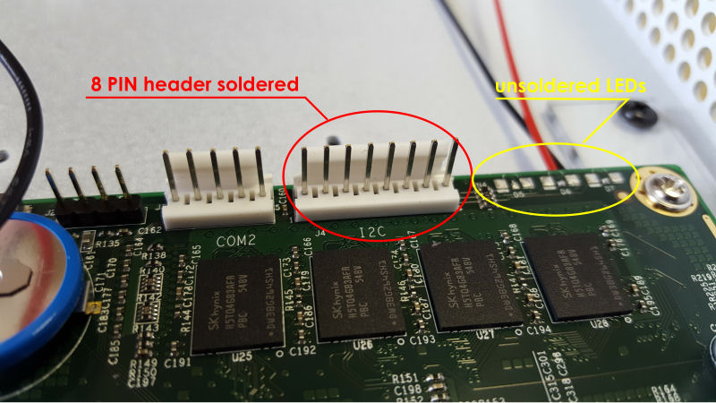
Without this step the report LEDs will not light up. At least the lighting level will be very, very low.
8 pin connector soldered and the 3 LEDs of the motherboard unsoldered.
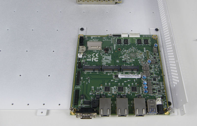
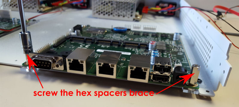
Step 3 - Fixing the motherboard and mounting the spacer braces of the LED report
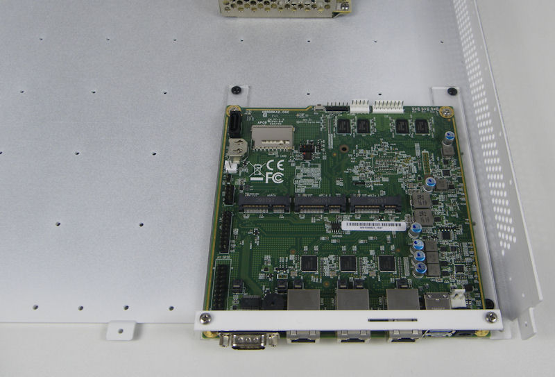
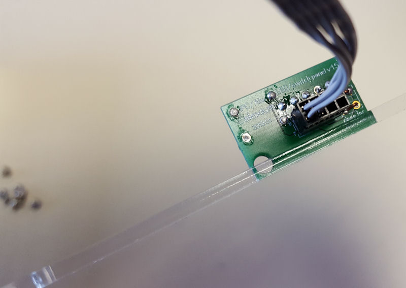
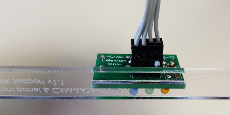
Step 4 - Mounting of the LED report
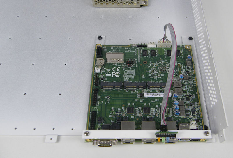
Step 5 - Connection of the LED report cable
Step 6 - Final mounting, overview